Hall Probe Circuit Diagram
Hall sensor circuit effect experimental gr next circuits A hall probe is placed near one end of a solenoid that has been wound Probes for hall effect measurements
hall effect circuit Page 2 : Sensors Detectors Circuits :: Next.gr
Schematic diagram of the hall probe detection system: current source Hall probe showing sensors (color online) (a) sketch of the probe assembly showing only two
Probe amplifier
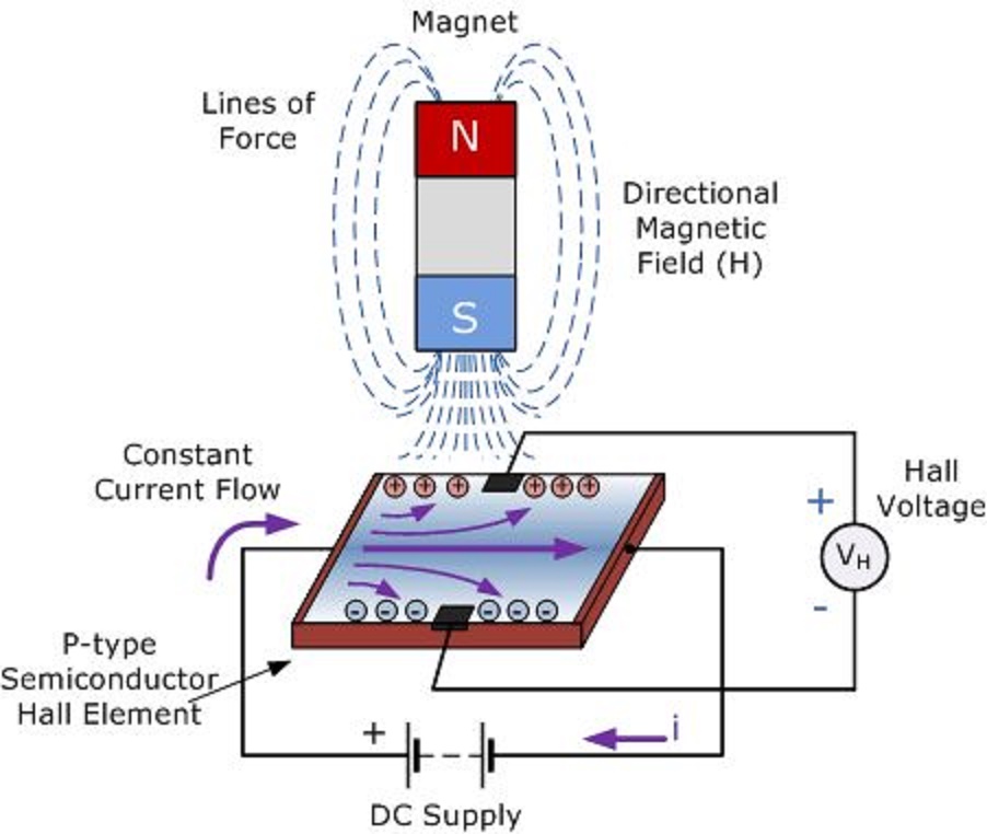
Probe physics solenoid wound softHall sensor effect principle magnetic works force semiconductor electronics Hall effect probes measurementsSchematic amplifier.
Probe physics measure caie practicalConstruction of the hall probe. What is hall effect sensor?Electrical and electronics engineering: hall effect sensor principals!!!.

Mj14 p52 q1 using hall probe to measure b
Linear hall-effect sensorSchematic diagram of the hall probe detection system: current source Hall effect circuit page 2 : sensors detectors circuits :: next.grColor online a plan-view image of the hall probe containing three.
Probe physics doubtsProbe containing scanning microscope Hall effect sensor circuit linear using diagram wiring sensors circuits amp op amplifier switch magnetic homemade opamp applicationSensor principals.

Physics 9702 doubts
Probe schematic amplifier .
.


